20 Theory of thermography
20.1 Introduction
The subjects of infrared radiation and the related technique of thermography are still new to many who will use an infrared
camera. In this section the theory behind thermography will be given.
20.2 The electromagnetic spectrum
The electromagnetic spectrum is divided arbitrarily into a number of wavelength regions, called bands, distinguished by the methods used to produce and detect the radiation. There is no fundamental difference between radiation
in the different bands of the electromagnetic spectrum. They are all governed by the same laws and the only differences are
those due to differences in wavelength.
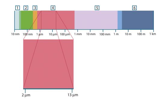
Figure 20.1 The electromagnetic spectrum. 1: X-ray; 2: UV; 3: Visible; 4: IR; 5: Microwaves; 6: Radiowaves.
Thermography makes use of the infrared spectral band. At the short-wavelength end the boundary lies at the limit of visual
perception, in the deep red. At the long-wavelength end it merges with the microwave radio wavelengths, in the millimeter
range.
The infrared band is often further subdivided into four smaller bands, the boundaries of which are also arbitrarily chosen.
They include: the near infrared (0.75–3 μm), the middle infrared (3–6 μm), the far infrared (6–15 μm) and the extreme infrared (15–100 μm). Although the wavelengths are given in μm (micrometers), other units are often still used to measure wavelength
in this spectral region, e.g. nanometer (nm) and Ångström (Å).
The relationships between the different wavelength measurements is:
20.3 Blackbody radiation
A blackbody is defined as an object which absorbs all radiation that impinges on it at any wavelength. The apparent misnomer
black relating to an object emitting radiation is explained by Kirchhoff’s Law (after Gustav Robert Kirchhoff, 1824–1887), which states that a body capable of absorbing all radiation at any wavelength is equally capable in the emission
of radiation.
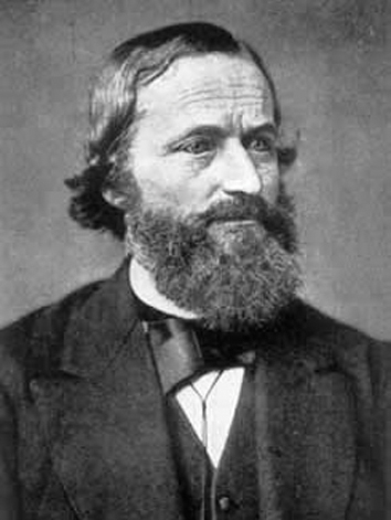
Figure 20.2 Gustav Robert Kirchhoff (1824–1887)
The construction of a blackbody source is, in principle, very simple. The radiation characteristics of an aperture in an isotherm
cavity made of an opaque absorbing material represents almost exactly the properties of a blackbody. A practical application
of the principle to the construction of a perfect absorber of radiation consists of a box that is light tight except for an
aperture in one of the sides. Any radiation which then enters the hole is scattered and absorbed by repeated reflections so
only an infinitesimal fraction can possibly escape. The blackness which is obtained at the aperture is nearly equal to a blackbody
and almost perfect for all wavelengths.
By providing such an isothermal cavity with a suitable heater it becomes what is termed a cavity radiator. An isothermal cavity heated to a uniform temperature generates blackbody radiation, the characteristics of which are determined
solely by the temperature of the cavity. Such cavity radiators are commonly used as sources of radiation in temperature reference
standards in the laboratory for calibrating thermographic instruments, such as a
FLIR Systems
camera for example.
If the temperature of blackbody radiation increases to more than 525°C (977°F), the source begins to be visible so that it appears to the eye no longer black. This is the incipient red heat temperature
of the radiator, which then becomes orange or yellow as the temperature increases further. In fact, the definition of the
so-called color temperature of an object is the temperature to which a blackbody would have to be heated to have the same appearance.
Now consider three expressions that describe the radiation emitted from a blackbody.
20.3.1 Planck’s law
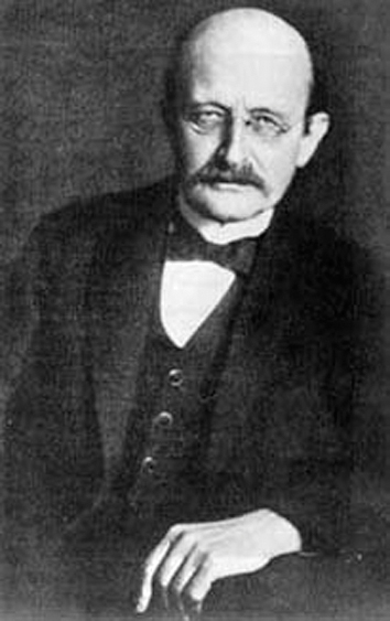
Figure 20.3 Max Planck (1858–1947)
Max Planck (1858–1947) was able to describe the spectral distribution of the radiation from a blackbody by means of the following formula:
where:
|
Wλb
|
Blackbody spectral radiant emittance at wavelength λ.
|
|
c
|
Velocity of light = 3 × 10⁸ m/s
|
|
h
|
Planck’s constant = 6.6 × 10⁻³⁴ Joule sec.
|
|
k
|
Boltzmann’s constant = 1.4 × 10⁻²³ Joule/K.
|
|
T
|
Absolute temperature (K) of a blackbody.
|
|
λ
|
Wavelength (μm).
|
Planck’s formula, when plotted graphically for various temperatures, produces a family of curves. Following any particular
Planck curve, the spectral emittance is zero at λ = 0, then increases rapidly to a maximum at a wavelength λmax
and after passing it approaches zero again at very long wavelengths. The higher the temperature, the shorter the wavelength
at which maximum occurs.
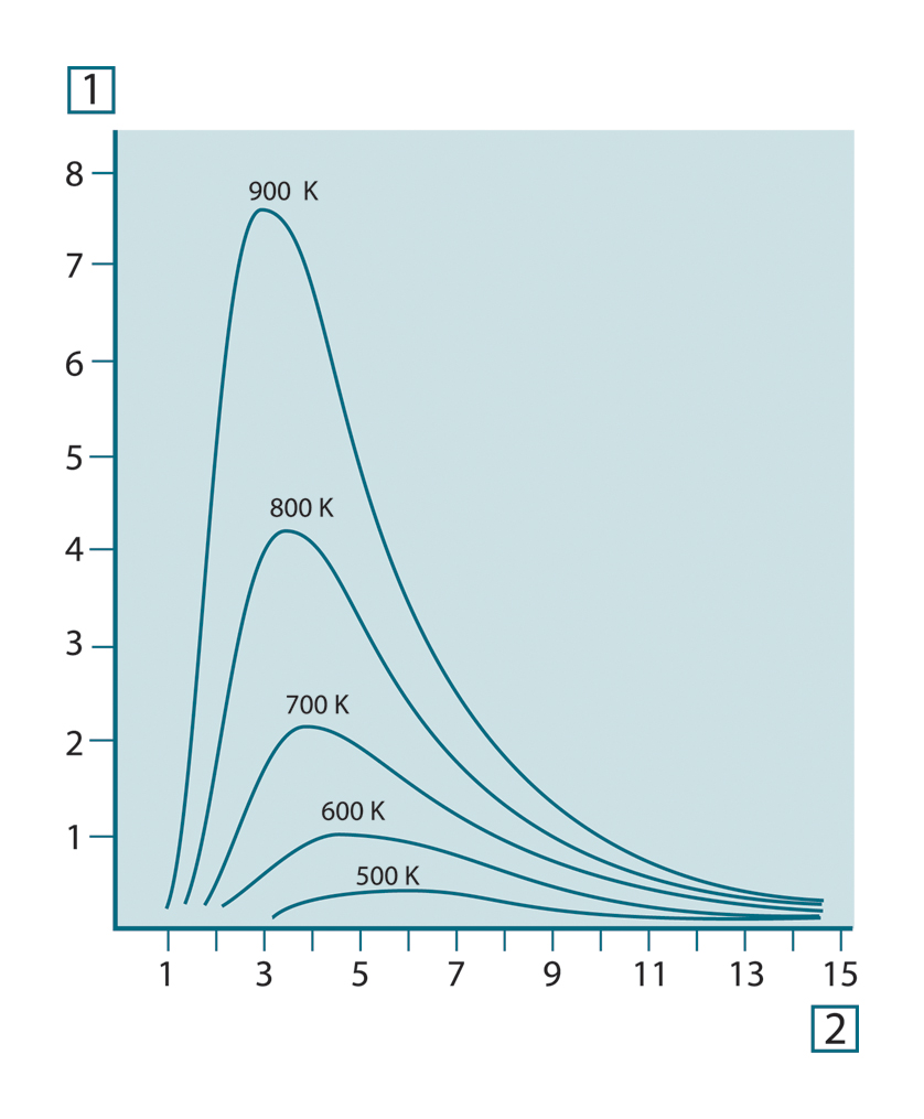
Figure 20.4 Blackbody spectral radiant emittance according to Planck’s law, plotted for various absolute temperatures. 1: Spectral radiant emittance (W/cm2 × 103(μm)); 2: Wavelength (μm)
20.3.2 Wien’s displacement law
By differentiating Planck’s formula with respect to λ, and finding the maximum, we have:
This is Wien’s formula (after Wilhelm Wien, 1864–1928), which expresses mathematically the common observation that colors vary from red to orange or yellow as the temperature
of a thermal radiator increases. The wavelength of the color is the same as the wavelength calculated for λmax
. A good approximation of the value of λmax
for a given blackbody temperature is obtained by applying the rule-of-thumb 3 000/T μm. Thus, a very hot star such as Sirius
(11 000 K), emitting bluish-white light, radiates with the peak of spectral radiant emittance occurring within the invisible
ultraviolet spectrum, at wavelength 0.27 μm.
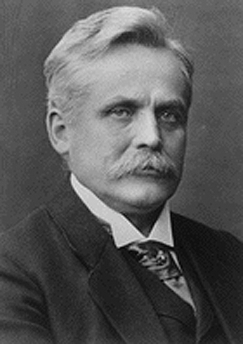
Figure 20.5 Wilhelm Wien (1864–1928)
The sun (approx. 6 000 K) emits yellow light, peaking at about 0.5 μm in the middle of the visible light spectrum.
At room temperature (300 K) the peak of radiant emittance lies at 9.7 μm, in the far infrared, while at the temperature of
liquid nitrogen (77 K) the maximum of the almost insignificant amount of radiant emittance occurs at 38 μm, in the extreme
infrared wavelengths.
Figure 20.6 Planckian curves plotted on semi-log scales from 100 K to 1000 K. The dotted line represents the locus of maximum radiant emittance at each temperature as described by Wien's displacement law. 1: Spectral radiant emittance (W/cm2 (μm)); 2: Wavelength (μm).
20.3.3 Stefan-Boltzmann's law
By integrating Planck’s formula from λ = 0 to λ = ∞, we obtain the total radiant emittance (Wb) of a blackbody:
This is the Stefan-Boltzmann formula (after Josef Stefan, 1835–1893, and Ludwig Boltzmann, 1844–1906), which states that the total emissive power of a blackbody is proportional to the fourth power of its absolute
temperature. Graphically, Wb
represents the area below the Planck curve for a particular temperature. It can be shown that the radiant emittance in the
interval λ = 0 to λmax
is only 25% of the total, which represents about the amount of the sun’s radiation which lies inside the visible light spectrum.
Figure 20.7 Josef Stefan (1835–1893), and Ludwig Boltzmann (1844–1906)
Using the Stefan-Boltzmann formula to calculate the power radiated by the human body, at a temperature of 300 K and an external
surface area of approx. 2 m2, we obtain 1 kW. This power loss could not be sustained if it were not for the compensating absorption of radiation from
surrounding surfaces, at room temperatures which do not vary too drastically from the temperature of the body – or, of course,
the addition of clothing.
20.3.4 Non-blackbody emitters
So far, only blackbody radiators and blackbody radiation have been discussed. However, real objects almost never comply with
these laws over an extended wavelength region – although they may approach the blackbody behavior in certain spectral intervals.
For example, a certain type of white paint may appear perfectly white in the visible light spectrum, but becomes distinctly gray at about 2 μm, and beyond 3 μm it is almost black.
There are three processes which can occur that prevent a real object from acting like a blackbody: a fraction of the incident
radiation α may be absorbed, a fraction ρ may be reflected, and a fraction τ may be transmitted. Since all of these factors
are more or less wavelength dependent, the subscript λ is used to imply the spectral dependence of their definitions. Thus:
- The spectral absorptance αλ = the ratio of the spectral radiant power absorbed by an object to that incident upon it.
- The spectral reflectance ρλ = the ratio of the spectral radiant power reflected by an object to that incident upon it.
- The spectral transmittance τλ = the ratio of the spectral radiant power transmitted through an object to that incident upon it.
The sum of these three factors must always add up to the whole at any wavelength, so we have the relation:
For opaque materials τλ
= 0 and the relation simplifies to:
Another factor, called the emissivity, is required to describe the fraction ε of the radiant emittance of a blackbody produced
by an object at a specific temperature. Thus, we have the definition:
The spectral emissivity ελ
= the ratio of the spectral radiant power from an object to that from a blackbody at the same temperature and wavelength.
Expressed mathematically, this can be written as the ratio of the spectral emittance of the object to that of a blackbody
as follows:
Generally speaking, there are three types of radiation source, distinguished by the ways in which the spectral emittance of
each varies with wavelength.
- A blackbody, for which ελ = ε = 1
- A graybody, for which ελ = ε = constant less than 1
- A selective radiator, for which ε varies with wavelength
According to Kirchhoff’s law, for any material the spectral emissivity and spectral absorptance of a body are equal at any
specified temperature and wavelength. That is:
From this we obtain, for an opaque material (since αλ + ρλ = 1):
For highly polished materials ελ
approaches zero, so that for a perfectly reflecting material (i.e. a perfect mirror) we have:
For a graybody radiator, the Stefan-Boltzmann formula becomes:
This states that the total emissive power of a graybody is the same as a blackbody at the same temperature reduced in proportion
to the value of ε from the graybody.
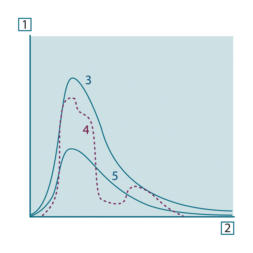
Figure 20.8 Spectral radiant emittance of three types of radiators. 1: Spectral radiant emittance; 2: Wavelength; 3: Blackbody; 4: Selective radiator; 5: Graybody.
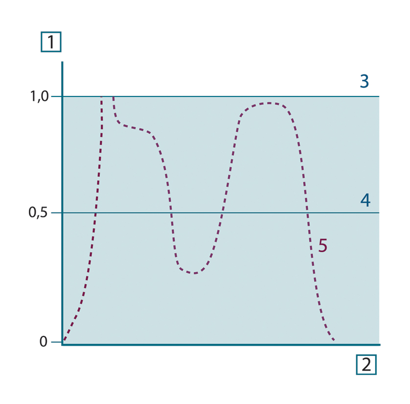
Figure 20.9 Spectral emissivity of three types of radiators. 1: Spectral emissivity; 2: Wavelength; 3: Blackbody; 4: Graybody; 5: Selective radiator.
20.4 Infrared semi-transparent materials
Consider now a non-metallic, semi-transparent body – let us say, in the form of a thick flat plate of plastic material. When
the plate is heated, radiation generated within its volume must work its way toward the surfaces through the material in which
it is partially absorbed. Moreover, when it arrives at the surface, some of it is reflected back into the interior. The back-reflected
radiation is again partially absorbed, but some of it arrives at the other surface, through which most of it escapes; part
of it is reflected back again. Although the progressive reflections become weaker and weaker they must all be added up when
the total emittance of the plate is sought. When the resulting geometrical series is summed, the effective emissivity of a
semi-transparent plate is obtained as:
When the plate becomes opaque this formula is reduced to the single formula:
This last relation is a particularly convenient one, because it is often easier to measure reflectance than to measure emissivity
directly.