11 Description — FLIR EST Kiosk
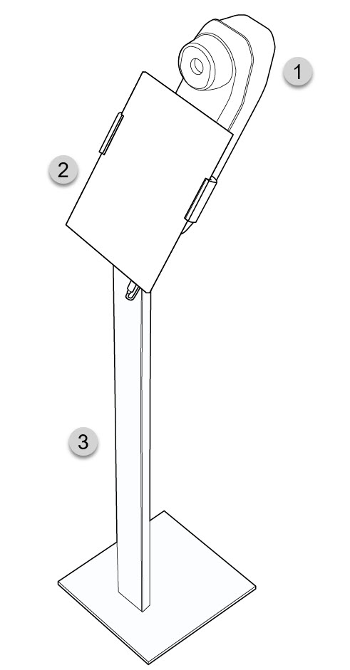
11.1 System parts

- Camera unit
- Tablet
- Stand
11.2 Camera web interface
The FLIR EST Kiosk camera has a web interface. If the camera has been reset to factory default settings, you must log in to the camera web interface
to re-configure the firewall settings.
To log in to the camera web interface, you need to find the camera on the IP network by using the FLIR IP Config software.
11.2.1 Install FLIR IP Config
FLIR IP Config is a software used to detect cameras in an IP network.
FLIR IP Config is pre-installed on the tablet. If FLIR IP Config has been removed, you have to re-install the software.
- Go to https://flir.custhelp.com/ .
- In the search field, enter “FLIR IP Config” and then click the Search button. In the search results, click the Download FLIR IP Config link.
- Download the latest version of FLIR IP Config (zip file).
- Unzip the file and run the *.exe file.
- Follow the instructions in the installation wizard.
To install the FLIR IP Config software, do the following:
11.2.2 Open the camera web interface
To log in to the camera web interface, you need the administrator password. The password is available on the camera calibration
certificate, which is included in the FLIR EST Kiosk package.
- Start the FLIR IP Config software by double-tapping the desktop icon.
- The FLIR IP Config automatically scans for cameras. When a camera is detected, FLIR IP Config displays the IP address of the camera.
- Double-tap the camera in FLIR IP Config. This opens the camera login page in a web browser.
- Log in with the username admin and the default administrator password available on the camera calibration certificate. This displays the web interface of the camera.
To open the camera web interface, do the following:
11.2.3 Firewall configuration
The camera is pre-configured to open up the firewall. If the camera has been reset to factory default settings, you must configure
the firewall settings.
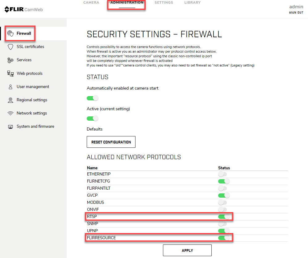
- Log in to the camera web interface, see section 11.2.2 Open the camera web interface .
- Go to the Administration tab and select Firewall.
- Make sure the RTSP switch is set to ON.
- Make sure the FLIRRESOURCE switch is set to ON.
- Tap Apply at the bottom of the page.
To configure the firewall settings, do the following:

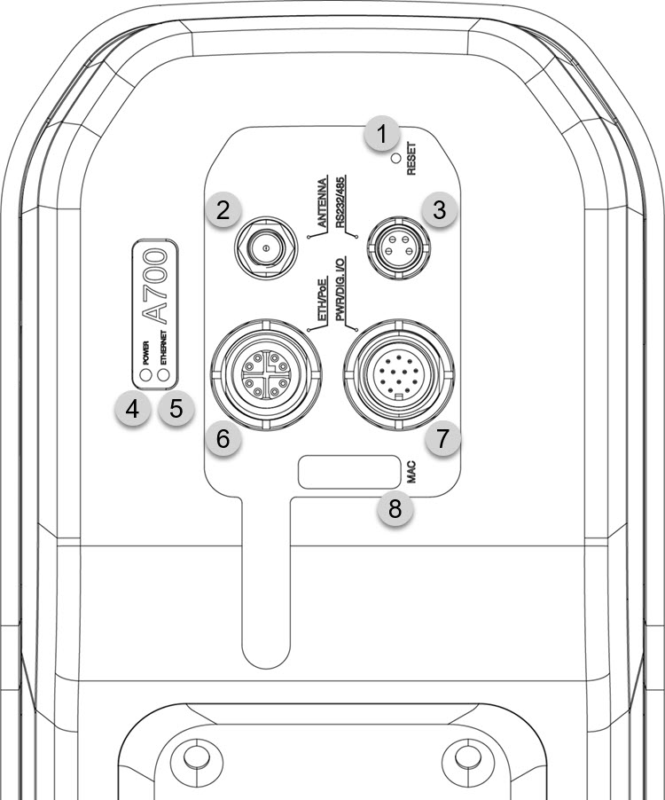
11.3 Camera connectors and buttons

- Factory reset button.
- Antenna.
- RS232/485 connector.
- Power/error indicator LED (blue/red).
- Ethernet communication indicator LED (green).
- Ethernet/Power over Ethernet connector.
- Power and Digital I/O connector.
- MAC address label.
11.3.1 Factory reset button
|
Factory reset button depression time period |
Indicator LED status |
Explanation |
|---|---|---|
|
> 1 second
|
A continuous red light
|
When the factory reset button is released:
|
|
> 4 seconds
|
A flashing red light
|
When the factory reset button is released:
|
|
> 10 seconds
|
A rapidly flashing red light
|
When the factory reset button is released:
|
11.3.2 Power/error indicator LED and power modes
|
Indicator LED status |
Explanation |
|---|---|
|
A flashing blue light.
|
Normal operation.
|
11.3.3 Ethernet communication indicator LED
|
Indicator LED status |
Explanation |
|---|---|
|
A flashing green light
|
The camera is connected to a network and the network activity is indicated.
|
|
No light (i.e., it is switched off).
|
The camera is not connected to any network.
|
11.3.4 Digital I/O
For information about the Digital I/O connector, refer to the FLIR A500/A700–EST User’s manual (available online at
http://support.flir.com/resources/ds6g
).