10 Camera web interface
10.1 Supported browsers
- Google Chrome 77 and higher,
- Microsoft Edge 17 and higher,
- Mozilla Firefox 69 and higher.
10.2 Login
-
Do one of the following:
- Identify your camera by the MAC address (printed on the back of the camera) in FLIR IP Config, and then double-click it.
- Type the IP address of your camera into the address bar of a web browser.
This displays the login view. - When logging in for the first time, log in with the username admin and the default administrator password provided by FLIR (available on the camera calibration certificate). It is possible to change the administrator password after the first login, and some cameras will require this.
10.3 Navigation
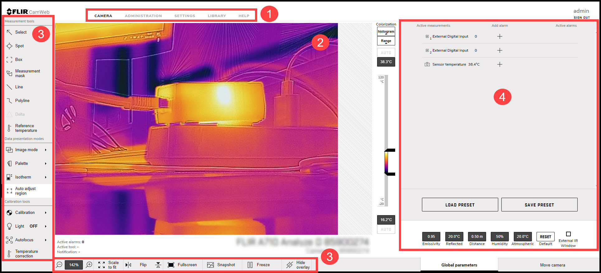
Figure 10.1 Camera web user interface
-
Tabs
Available tabs depend on user type;
- An admin sees the Camera, Administration, Settings, and Library tabs.
- A user sees the Camera, Settings, and Library tabs.
- A viewer sees the Camera tab.
-
Live image
This is where the live image is presented of what the camera is currently targeting.
-
Toolbar
The toolbar options are grouped into the following categories;
- Measurement tools
- Data presentation modes
- Calibration tools
- View modes
-
Active measurements
Any measurement tools added to the image are displayed and managed from here.
10.4 Camera tab
10.4.1 Working with measurement tools
10.4.1.1 Spot
To add a spot measurement tool, follow this procedure:
On the toolbar and in the Measurement tools section, click Spot.
In the image, click to insert the spot. The tool is labeled with a number, and it is also displayed in the Active measurements section.
To move the tool, click and hold the tool label in the image, and then move it into position.
To configure Settings for the tool, click
 next to the tool in the Active measurements section. This displays the Settings dialog box.
- To change the label of the tool, change the Spot name.
- Use the Autofocus range option to set autofocus on the tool.
- To set local parameters for the tool, see section 10.4.3.2 Local parameters .
To associate an alarm with the tool, see section 10.4.2 Working with alarms .
To remove the tool, click Settings
next to the tool in the Active measurements section, and then click Delete measurement.
10.4.1.2 Box
To add a box measurement tool, follow this procedure:
On the toolbar and in the Measurement tools section, click Box.
In the image, click and then draw a box of a desired size. The tool is labeled with a number, and it is also displayed in the Active measurements section.
To move the tool, click and hold the tool label in the image, and then move it into position.
To resize the tool, click and hold one of the corners of the box in the image, and then move it to the desired size and shape.
To configure Settings for the tool, click
next to the tool in the Active measurements section. This displays the Settings dialog box.
- To change the label of the tool, change the Box name.
- To select what measurement results to display, use the Maximum, Minimum, and Average check boxes.
- Use the Local options to set autofocus on the tool.
- Use the Local options to adjust the temperature scale according to the temperatures of the tool. For more information, see section 10.4.10 Adjusting the temperature scale .
- To display how much of the tool is covered by an isotherm, select the Iso check box. This setting is only applicable if you have selected a color alarm (isotherm). For more information, see section 10.4.5.2 Isotherms .
- To set local parameters for the tool, see section 10.4.3.2 Local parameters .
To associate an alarm with the tool, see section 10.4.2 Working with alarms .
To remove the tool, click Settings
next to the tool in the Active measurements section, and then click Delete measurement.
10.4.1.3 Measurement mask
To add a measurement mask tool, follow this procedure:
On the toolbar and in the Measurement tools section, click Measurement mask.
In the image, click to insert the starting point of the mask. Move the pointer and click to insert the next point. Continue until you have the captured the desired shape. Finish by clicking the starting point. The tool is labeled with a number, and it is also displayed in the Active measurements section.
To configure Settings for the tool, click
next to the tool in the Active measurements section. This displays the Settings dialog box.
- To change the label of the tool, change the Mask name.
- To select what measurement results to display, use the Maximum, Minimum, and Average check boxes.
- Use the Local options to set autofocus on the tool.
- Use the Local options to adjust the temperature scale according to the temperatures of the tool. For more information, see section 10.4.10 Adjusting the temperature scale .
- To display how much of the tool is covered by an isotherm, select the Iso check box. This setting is only applicable if you have selected a color alarm (isotherm). For more information, see section 10.4.5.2 Isotherms .
- To add another shape to the tool, click Draw and then draw the shape.
- To set local parameters for the tool, see section 10.4.3.2 Local parameters .
To associate an alarm with the tool, see section 10.4.2 Working with alarms .
To remove the tool, click Settings
next to the tool in the Active measurements section, and then click Delete measurement.
10.4.1.4 Line
To add a line measurement tool, follow this procedure:
On the toolbar and in the Measurement tools section, click Line.
In the image, click a starting point and then draw the line to the desired length. The tool is labeled with a number, and it is also displayed in the Active measurements section.
To move the tool, click and hold the tool label in the image, and then move it into position.
To change the length of the tool, click one of the end points, and then move it to the desired length.
To configure Settings for the tool, click
next to the tool in the Active measurements section. This displays the Settings dialog box.
- To change the label of the tool, change the Line name.
- To select what measurement results to display, use the Maximum, Minimum, and Average check boxes.
- Use the Local options to set autofocus on the tool.
- Use the Local options to adjust the temperature scale according to the temperatures of the tool. For more information, see section 10.4.10 Adjusting the temperature scale .
- To set local parameters for the tool, see section 10.4.3.2 Local parameters .
- To add a temperature graph under the live image representing the tool, click the Display temperature graph check box.
To associate an alarm with the tool, see section 10.4.2 Working with alarms .
To remove the tool, click Settings
next to the tool in the Active measurements section, and then click Delete measurement.
10.4.1.5 Polyline
To add a polyline measurement tool, follow this procedure:
On the toolbar and in the Measurement tools section, click Polyline.
In the image, click to insert the starting point of the polyline. Move the pointer and click to insert the next point. Continue until you have the desired shape. Finish by clicking Confirm. The tool is labeled with a number, and it is also displayed in the Active measurements section.
To move the tool, click and hold the tool label in the image, and then move it into position.
To configure Settings for the tool, click
next to the tool in the Active measurements section. This displays the Settings dialog box.
- To change the label of the tool, change the Polyline name.
- To select what measurement results to display, use the Maximum, Minimum, and Average check boxes.
- Use the Local options to set autofocus on the tool.
- Use the Local options to adjust the temperature scale according to the temperatures of the tool. For more information, see section 10.4.10 Adjusting the temperature scale .
- To set local parameters for the tool, see section 10.4.3.2 Local parameters .
- To add a temperature graph of the tool under the live image, click the Display temperature graph check box.
To associate an alarm with the tool, see section 10.4.2 Working with alarms .
To remove the tool, click Settings
next to the tool in the Active measurements section, and then click Delete measurement.
10.4.1.6 Delta
To add a delta measurement tool, follow this procedure:
On the toolbar and in the Measurement tools section, click Delta. The tool is displayed in the Active measurements section.
In the Active measurements section, click Settings
. The Delta settings dialog box appears.
To change the label of the tool, change the Delta name.
In the Variable 1 and Variable 2 lists, select the measurement results you want to use in the calculation.
Click Save changes.
10.4.1.7 Reference temperature
To add a reference temperature, follow this procedure:
On the toolbar and in the Measurement tools section, click Reference temperature. The tool is displayed in the Active measurements section.
In the Active measurements section, click Settings
. The Reference temperature dialog box appears.
To change the label, change the Reftemp name.
In the Value box, type the temperature to be used as reference.
Click Save changes.
10.4.2 Working with alarms
10.4.2.1 Setting an alarm based on a measurement result
To configure an alarm based on the measurement result from a spot, box, or delta measurement tool, follow this procedure:
In the Active Measurements section, click the plus sign under Add alarm next to the measurement result to be used for the alarm. The Add alarm dialog box appears.
In the Alarm label section, type an Alarm name.
In the Trigger section, select the Condition and temperatures that will trigger this alarm:
|
Triggers an alarm when the temperature is above the specified Threshold value. Also type a Hysteresis value.
|
|
Triggers an alarm when the temperature is within the specified Min value and Max value.
|
Hysteresis is the interval within which the temperature value is allowed to vary without causing a change in the trigger. If the threshold is set above 30.0°C and the hysteresis is set at 2.0°C, the trigger goes high when the temperature rises above 30.0°C and stays high until the temperature drops below 28.0°C. In contrast, if the threshold is set below 30.0°C, and the same hysteresis value is kept, the trigger goes high if the temperature drops below 30.0°C and stays high until the temperature rises above 32.0°C.
In the Threshold time box, type the amount of time that has to pass before an alarm is triggered. This can be used to avoid false alarms.
In the Action section, select which actions the camera will perform when an alarm is triggered:
|
Automatically sends the captured Image, Result, or Video to the recipients defined in Settings > Alarm recipients. For more information, see section
10.6.2 Alarm recipients
.
|
|
Automatically sends the captured Image or Video to the FTP site defined in Settings > Alarm recipients. For more information, see section
10.6.2 Alarm recipients
.
|
|
Automatically saves the captured Image or Video to the memory of the camera.
|
|
Temporarily disables the periodic calibration while the image/video is being captured.
|
The image/video can later be viewed and managed under the Library tab:
- the captured image frame that triggered the alarm,
- the 5 second video sequence when the alarm was triggered.
When completed, click Set alarm. The alarm is now listed under Active alarms.
10.4.2.2 Setting an alarm based on the digital input
To configure an alarm based on the digital input, follow this procedure:
In the Active Measurements section, click the plus sign under Add alarm next to the digital input result to be used for the alarm. The Alarm dialog box appears.
In the Alarm label section, type an Alarm name.
In the Trigger section and in the Value list; select “0” to trigger the alarm on a low signal or select “1” to trigger on a high signal.
In the Action section, select which actions the camera will perform when an alarm is triggered:
|
Automatically sends the captured Image, Result, or Video to the recipients defined in Settings > Alarm recipients. For more information, see section
10.6.2 Alarm recipients
.
|
|
Automatically sends the captured Image or Video to the FTP site defined in Settings > Alarm recipients. For more information, see section
10.6.2 Alarm recipients
.
|
|
Automatically saves the captured Image or Video to the memory of the camera.
|
|
Temporarily disables the periodic calibration while the image/video is being captured.
|
The image/video can later be viewed and managed under the Library tab:
- the captured image frame that triggered the alarm,
- the 5 second video sequence when the alarm was triggered.
When completed, click Set alarm. The alarm is now listed under Active alarms.
10.4.2.3 Setting an alarm based on sensor temperature
The internal temperature sensor can act as a thermometer for the ambient temperature. To configure an alarm based on the internal temperature sensor, follow this procedure:
In the Active Measurements section, click the plus sign under Add alarm next to the Sensor temperature. The Alarm dialog box appears.
In the Alarm label section, type an Alarm name.
In the Trigger section, select the Condition and temperatures that will trigger this alarm:
|
Triggers an alarm when the temperature is above the specified Threshold value. Also type a Hysteresis value.
|
|
Triggers an alarm when the temperature is within the specified Min value and Max value.
|
Hysteresis is the interval within which the temperature value is allowed to vary without causing a change in the trigger. If the threshold is set above 30.0°C and the hysteresis is set at 2.0°C, the trigger goes high when the temperature rises above 30.0°C and stays high until the temperature drops below 28.0°C. In contrast, if the threshold is set below 30.0°C, and the same hysteresis value is kept, the trigger goes high if the temperature drops below 30.0°C and stays high until the temperature rises above 32.0°C.
In the Threshold time box, type the amount of time that has to pass before an alarm is triggered. This can be used to avoid false alarms.
In the Action section, select which actions the camera will perform when an alarm is triggered:
|
Automatically sends the captured Image, Result, or Video to the recipients defined in Settings > Alarm recipients. For more information, see section
10.6.2 Alarm recipients
.
|
|
Automatically sends the captured Image or Video to the FTP site defined in Settings > Alarm recipients. For more information, see section
10.6.2 Alarm recipients
.
|
|
Automatically saves the captured Image or Video to the memory of the camera.
|
|
Temporarily disables the periodic calibration while the image/video is being captured.
|
The image/video can later be viewed and managed under the Library tab:
- the captured image frame that triggered the alarm,
- the 5 second video sequence when the alarm was triggered.
When completed, click Set alarm. The alarm is now listed under Active alarms.
10.4.3 Changing object parameters
-
Emissivity
How much radiation an object emits, compared with the radiation of a theoretical reference object at the same temperature (called a “blackbody”). The opposite of emissivity is reflectivity. The emissivity determines how much of the radiation originates from the object as opposed to being reflected by it.
-
Reflected temperature
This is used when compensating for the radiation from the surroundings reflected by the object into the camera. This property of the object is called reflectivity.
-
Distance
The distance between the camera and the object of interest.
-
Relative humidity
The relative humidity of the air between the camera and the object of interest.
-
Atmospheric temperature
The temperature of the air between the camera and the object of interest.
-
External IR window
Used if any protective windows etc. are set up between the camera and the object of interest. When the setting is on, the following parameters can be set:
- Transmission: How much of the thermal radiation passes through the window.
- Temperature: The temperature of the window.
10.4.3.1 Global parameters
To change the global parameters, follow this procedure:
In the bottom right corner of the screen, click to select the parameter to change.
Change the parameter to the desired value, and then press Enter or click anywhere on the screen.
To reset the global parameters to the default values provided by FLIR, click Reset.
10.4.3.2 Local parameters
In the Active measurements section, click Settings
next to the tool for which you want to change the parameters. The Settings dialog box appears.
To activate the use of local parameters, select the Local parameters check box. The values for the Emissivity, Reflected temperature, and Distance parameters are now editable.
To deactivate the use of local parameters, deselect the Local parameters check box.
When completed, click Save changes.
10.4.4 Working with image modes
-
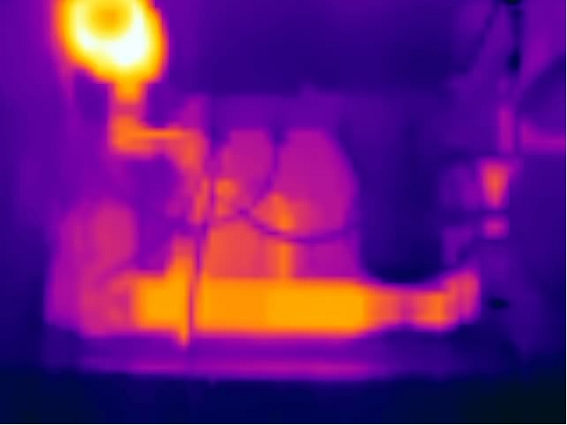
Thermal: The camera displays a fully thermal image.
![Graphic]()
-
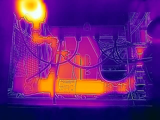
MSX (Multi Spectral Dynamic Imaging): The camera displays the thermal image where details from the visual image have been added.
![Graphic]()
-
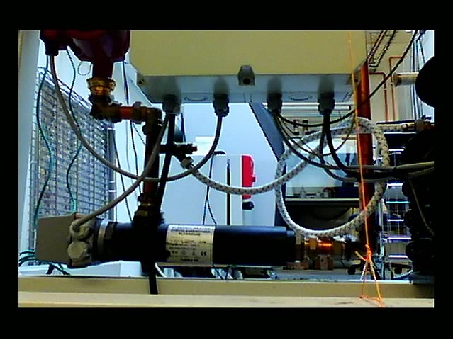
Visual: The camera displays the visual image captured by the visual camera.
![Graphic]()
- FSX (Flexible Scene Enhancement): The camera displays the thermal image with enhanced image details. This image mode is useful when higher contrast is required, for example when the camera is used in a surveillance application.
On the toolbar and in the Data presentation modes section, click Image mode.
Select one of the available image modes.
10.4.5 Colorizing the image
10.4.5.1 Palette
To change the palette, follow this procedure:
On the toolbar and in the Data presentation modes, click Palette.
Select one of the available palettes.
10.4.5.2 Isotherms
-
Above
Applies a contrasting color (red) to all pixels with a temperature above the specified temperature level.
-
Below
Applies a contrasting color (blue) to all pixels with a temperature below the specified temperature level.
-
Interval
Applies a contrasting color (yellow) to all pixels with a temperature between two specified temperature levels.
To configure an isotherm, follow this procedure:
On the toolbar and in the Data presentation modes section, click Isotherm.
Select one of the available isotherms.
When a color alarm is selected, it is displayed in the Active measurements section. Also, a temperature indicator is added to the left side of the temperature scale located to the right of the image.
To change the threshold temperature, click Settings
next to the isotherm in the Active measurements section. The Settings dialog box appears.
In the Range section, set the threshold temperature of the isotherm:
- Above; type a threshold temperature in the From box.
- Below; type a threshold temperature in the To box.
- Interval; type the interval temperatures in the To and From boxes.
Optionally, change the contrasting color in the Highlight color section.
When completed, click Save changes.
10.4.6 Auto-adjust region
To configure an auto-adjust region, follow this procedure:
On the toolbar and in the Data presentation modes section, click Auto-adjust region.
In the image, click and then draw a region of a desired size.
To move the region, click and hold the region label in the image, and then move it into position.
To resize the region, click and hold one of the corners of the region in the image, and then move it to the desired size and shape.
To remove the region, click X in the region label.
10.4.7 Calibrating the camera
10.4.7.1 Automatic calibration
To set the automatic calibration, follow this procedure:
On the toolbar and in the Calibration tools section, click Calibration. This displays a list of calibration options.
Click one of the options:
|
when needed.
|
|
approximately every 10 minutes, or when needed.
|
|
approximately every 30 minutes, or when needed.
|
|
approximately every 60 minutes, or when needed.
|
|
at any set interval.
|
|
never (automatic calibration disabled).
|
While the automatic calibration is in progress, the Notification text Calibration in progress ... is temporarily displayed under the live image.
10.4.7.2 Manual calibration
To perform a manual calibration, follow this procedure:
On the toolbar and in the Calibration tools section, click Calibration. This displays a list of calibration options.
Click Calibrate now.
While the manual calibration is in progress, the Notification text Calibration in progress ... is temporarily displayed under the image on the screen
10.4.8 Using the camera lamp
On the toolbar and in the Calibration tools section, click Light.
Click ON or OFF.
10.4.9 Changing the temperature range
10.4.10 Adjusting the temperature scale
To change the maximum temperature level, type the temperature in the upper temperature scale box. As an alternative, click and hold the upper temperature bar on the scale, and then move it into position. Watch the temperature in the scale box change as you move the bar.
To change the minimum temperature level, type the temperature in the lower temperature scale box.As an alternative, click and hold the lower temperature bar on the scale, and then move it into position. Watch the temperature in the scale box change as you move the bar.
To return to auto-adjustment, click the Auto button(s).
10.4.11 Flipping the image
On the toolbar and in the View modes section, click ![]() to flip the image horizontally or click
to flip the image horizontally or click ![]() to flip the image vertically.
to flip the image vertically.
10.4.12 Full screen view
To view the image in full screen, follow this procedure:
On the toolbar and in the View modes section, click Full screen.
To return to normal view, press the Esc (Escape) key on the computer keyboard.
10.4.13 Saving a snapshot
To take a snapshot, follow this procedure:
On the toolbar and in the View modes section, click Snapshot.
The Notification text Snapshot stored is temporarily displayed under the live image.
10.4.14 Pausing the live image stream
To pause or freeze the live image stream, follow this procedure:
On the toolbar and in the View modes section, click Freeze.
To resume the live image stream, click Unfreeze.
10.4.15 Hiding the overlay graphics
To hide all overlay graphics in the live image, follow this procedure:
On the toolbar and in the View modes section, click Hide overlay.
To show any hidden overlay graphics, click Show overlay.
10.4.16 Camera presets
10.4.16.1 Saving a preset
To save the current camera setup, follow this procedure:
In the Active measurements section, click Save preset.
10.4.16.2 Loading a preset
To load a saved preset file, follow this procedure:
In the Active measurements section, click Load preset. The standard Windows Open dialog box appears.
Browse to the Downloads folder (or to the folder where you have stored the preset files).
Select the file, and then click Open. This loads and applies the presets.
10.5 Administration tab
10.5.1 Firewall
10.5.2 SSL certificates
10.5.3 Services
-
Ethernet/IP
Enable this service when the camera is to communicate using industrial protocols such as Modbus TCP and Ethernet/IP. The camera can be used as either a Modbus client or a Modbus server. The settings for the Modbus client are located under the Settings tab. If the camera should be used as a Modbus server, the registers can be downloaded from the FLIR Customer support site. -
Pantilt server
Enable this service when the camera is connected to a Pan & Tilt unit. If the camera is connected to the unit using an RS-232/485 interface, it can control the unit from the Camera tab or by using ONVIF. -
httpResource
The httpResource service is an old way of controlling the camera. It should only be enabled if legacy FLIR software is used. -
ONVIF
Enable this service when the camera is to communicate with Video Management Systems (VMS) over ONVIF. If the service is disabled, the camera will not be discovered by third-party VMS. Note that the Advanced configuration is required on the camera for ONVIF to work.
After enabling the service, also click Apply to initialize it. When enabled, settings for the ONVIF users can be managed. -
ONVIF users
This section controls the ONVIF users and credentials, and it is only accessible if the ONVIF service is active.
Default credentials are; user name = fliruser and password = 3vlig.
10.5.4 Web protocols
10.5.5 User management
10.5.6 Regional settings
-
Get date and time from an SNTP Server (Simple Network Time Protocol):
Select the Enable check box, and then type the IP address of the SNTP Server in the Server address box.
-
Set date and time manually:
Select the correct Time zone in the list, and then type date and time information in the Year, Month, Day, Hour, Minute, and Second boxes.
-
Get date and time from your internet browser:
Click Read from browser.
-
Get date and time from your camera:
Click Read from camera.
- Celsius (C) and Fahrenheit (F)
- Meter (m) and Foot (ft)
10.5.7 Network settings
10.5.7.1 Ethernet setup
In the navigation pane, click Network settings.
Select one of the following:
- To automatically obtain an IP address for the camera, click Obtain IP address automatically (DHCP).
- To manually set an IP address for the camera, click Manual configuration, and then type valid network information in the IP, Subnet mask, and Gateway boxes.
Click Apply.
10.5.7.2 Wireless
In the navigation pane, click Network settings.
Click Server mode.
Type a Network name and a Password for accessing the network.
Click Share network.
The camera will now act as a “hotspot” that computers or tablets (with high resolution) can connect to. When a wireless connection
has been established, the camera will be available at the IP address 192.168.16.1.
In the navigation pane, click Network settings.
Click Client mode.
Click Scan networks.
Select one of the Available networks in the list, and then click Connect.
Type the Password for accessing the network, and then click Connect.
10.5.7.3 Streaming bit rate
In the navigation pane, click Network settings.
In the Streaming bit rate list, select one of the available bit rates.
Click Apply.
10.5.8 System and firmware
10.5.8.1 Restart camera
- In the navigation pane, click System and firmware.
- In the System section, click Restart camera. This displays a dialog box.
- In the dialog box, click OK. The camera will restart.
10.5.8.2 Reset camera to factory settings
- In the navigation pane, click System and firmware.
- In the System section, click Reset to factory settings. This displays a dialog box.
- In the dialog box, click OK. The camera will restart.
10.5.8.3 Upgrade camera firmware
- In the navigation pane, click System and firmware.
- In the System section, click Upgrade firmware. This displays a dialog box.
- Click Select file. The standard Windows Open dialog box appears.
- Browse to the location of the firmware file, select the file, and then click Open.
- Click Upgrade firmware.
- When the upgrade is completed, restart the camera.
10.5.9 SNMP settings
- Sink: The IP address to send trap messages to (trap receiver).
- Port number: Destination port used for trap (default port number is 162).
- Interval: An integer value (in seconds) between the heartbeat signals.
10.5.10 Multicast settings
10.6 Settings tab
- General settings
- Alarm recipients
- Scheduler
- MQTT
- Modbus
10.6.1 General settings
10.6.1.1 Camera ID
10.6.1.2 IP6x settings
-
Enable IP6x
When this setting is enabled, the two LED lamps at the front of the camera are disabled.
-
Disable manual focus ring
When this setting is enabled, it is impossible to use the manual focus ring of the camera. This is to prevent focus from changing due to, e.g., shock or vibrations.
-
External compensation
When this setting is enabled, compensation for the extra window (of the environmental housing, pan & tilt, or IP hood) in front of the infrared lens will be made. If needed, also change the External temperature.
10.6.1.3 Test Digital Input/Output
10.6.2 Alarm recipients
In the navigation pane, click Alarm recipients.
In the Alarm recipient e-mail box, type the e-mail address of the recipient.
In the Mail server setup box, type the IP address of the sending mail server.
If the sending mail server requires a login (mail server authentication), select the Authentication required check box, and then type the credentials in the User and Password boxes.
Click Apply.
In the navigation pane, click Alarm recipients.
In the FTP Server IP address box, type the IP address of the FTP server.
In the Folder box, type the path to the folder where you want to save the notifications. This can be useful if you have multiple cameras connected to the same FTP server.
In the User and Password boxes, type the credentials for FTP access.
Click Apply.
10.6.3 Scheduler
-
E-mail image
Send the image with overlay graphics.
-
E-mail result
Send a list of the active measurements and their respective temperatures.
-
Save image on FTP
Send the image with overlay graphics to an FTP server.
To schedule actions, follow this procedure:
In the navigation pane, click Scheduler.
Click the check boxes to select which Scheduled actions to use.
In the schedule, click the Active check box for the days that the action will run:
- To run the action once a day at a certain time, also click Once and then set an Action Time.
- To run the action several times a day, also click Repeat and then set a time Interval, a Start action time, and an End action time.
Click Apply.
In the FTP Server box, type the IP address of the FTP server.
In the FTP User and FTP Password boxes, type the credentials for the FTP access.
Click Apply.
In the Recipient e-mail box, type the e-mail address of the recipient.
In the Mail server box, type the IP address of the sending mail server.
In the Sender e-mail box, type the e-mail address of the sender.
If the sending mail server requires a login (mail server authentication), select the Authenticate mail check box, and then type the credentials in the User and Password boxes.
Click Apply.
10.6.4 MQTT
In the navigation pane, click MQTT.
Click the Enable MQTT check box.
Type the Broker host address and the TCP Broker Port used for the subscription transport.
Type the User and Password to login to the broker.
Select preferred Temperature unit in the list; Celsius (C), Fahrenheit (F), or Kelvin (K).
Select preferred Output format in the list; Json or Text.
Click Apply.
In your MQTT client of choice, set up a subscription for the topic corresponding to the information of interest. The topics will be updated when the data is updated, for example; if you subscribe to the topic FLIR/ec501-xxxxxx/alarm1, your MQTT client will receive an update when alarm1 is triggered and then another update when alarm1 criteria are no longer fulfilled. You can connect multiple cameras to the same MQTT broker.
10.6.5 Modbus
10.6.5.1 Digital out
In the navigation pane, click Modbus.
In the Digital out list, click Configure for the digital out number you want to use.
In the Digital output entry dialog box, type a Name of the entry. Also, type the IP Address, Device function ID, and Modbus Register address specific to the equipment.
Select Type specific to the equipment.
Click Apply.
To test the Modbus output, click Test which will activate the output for 5 seconds.
The digital out is now selectable in the Digital Out list when setting up alarms, see section 10.4.2 Working with alarms .
10.6.5.2 Analogue out
In the navigation pane, click Modbus.
In the Analogue out list, click Configure for the analogue out number you want to use.
In the Analogue output entry dialog box, type a Name of the entry.
Type the following information:
- Select which Measurement function and Update interval (ms) to use. The Update interval (ms) defines how often a new value is sent over Modbus to the external analogue output box.
- Type the IP Address, Device function ID, and Modbus Register address specific to the equipment.
- Select Type specific to the equipment.
- Type the Minimum temperature and the Maximum temperature to be represented.
- In the Data output at Minimum temperature and Data output at Maximum temperature boxes, type the digital values to be sent over Modbus representing the Minimum temperature and Maximum temperature, respectively.
Click Apply.
To test the Modbus output, click Test which will activate the output for 5 seconds.
10.7 Library tab
10.7.1 Managing images
In the navigation pane, click Images.
To display a preview of an image, click the thumbnail of the image.
As an alternative, click the image file name, and then click Preview.
To download an image, click the image file name, and then click Download.
To delete one or more images, click the image file name(s), and then click Delete.
10.7.2 Managing videos
In the navigation pane, click Videos.
To download a video, click the video file name, and then click Download.
To delete one or more videos, click the video file name(s), and then click Delete.
10.7.3 Managing logs
In the navigation pane, click Logs.
To enable logging of alarms, click the Logging enabled check box.
To download the generated logs as a zipped file, click Download log.
To delete the generated logs, click Clean log.